1325 Continuous Laser Drilling Machine
Fully automatic inline drilling for flat glass up to 2500 × 1500 mm
Hole diameter 2 – 65 mm with a telecentric F125 lens
Glass thickness 3 – 10 mm
Sheet sizes from 400 × 150 mm up to 2500 × 1500 mm
Irregular, stepped and tapered holes at any position on the sheet
The machine drills flat glass inline: sheets are fed in on rubber rollers, aligned and clamped, positioned by a vision system, drilled at any position within the working area, and passed on to the next station without an operator handling the glass.
Laser drilling is a non-contact process. It keeps edge chipping under control in micro-drilling, requires no water circulation, and produces irregular, stepped and tapered holes — while remaining straightforward to automate.
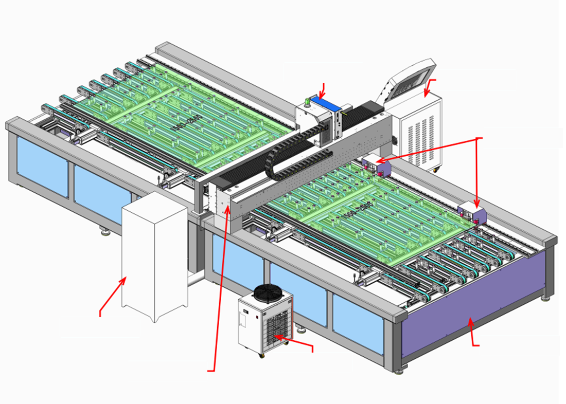
- 1Laser assembly
- 2Control cabinet
- 3Y1 gripper
- 4Dust collector
- 5Infeed direction
- 6Water chiller
- 7Marble beam
Non-contact processing
The laser never touches the glass and the process needs no water circulation, so there is no tool wear and no coolant to handle.
Controlled edge chipping
Edge chipping is held to ≤ 500 μm — the figure the machine is specified and accepted against.
Vision positioning per sheet
A vision system photographs each sheet before drilling, and the recognition position adjusts to different glass specifications.
Irregular and tapered holes
Irregular, stepped and tapered hole forms, at any position within the working area and with a variable number of holes per sheet.
Synchronised dust extraction
The extraction nozzle travels with the drilling head, keeping extraction effective at any position in the drilling area.
Continuous inline operation
Infeed, alignment, positioning, drilling and outfeed run as one automatic loop, so the machine sits inside a production line rather than beside it.
Applications and materials
Micro-drilling in brittle materials
Laser drilling for glass and comparable brittle materials, where non-contact processing keeps edge chipping under control.
Flexible hole layouts
Holes at any position within a 1500 × 2500 mm area, with a variable number of holes per sheet, driven from the imported drawing.
No water circulation
The process requires no water circulation, removing coolant handling and the contamination that comes with it.
Shapes mechanical tooling cannot cut
Irregular, stepped and tapered holes, produced without changing tooling between hole forms.
Material requirements
Suitable
- Untempered flat glass, with flatness variation < 2‰/m
- Single-coated glass
- Double-coated glass
- Glass mirrors
Not suitable
- Coloured glass
Hole position tolerance is ±0.5 mm, which requires the incoming sheet tolerance to be an order of magnitude smaller. Edge chipping is specified at ≤ 500 μm.
Machine cycle
- 1
Infeed
The feeding rubber rollers receive the sheet and move it to a predetermined position based on its length and width.
- 2
Lift
Once the sheet reaches position, the rollers of the lifting device rise.
- 3
Lateral alignment
The grippers clamp the sheet and transport it laterally to the fixed alignment edge.
- 4
Advance to the drilling zone
The Y1 and Y2 motion axes, positioned beneath the marble X-axis linear motor assembly, advance the clamped sheet to the drilling zone.
- 5
Vision positioning
The vision system photographs the sheet to establish its exact position before any hole is drilled.
- 6
Drilling
The laser drills the holes according to the imported pattern.
- 7
Index forward
On completion, the Y1 and Y2 axes advance the sheet to the next drilling position.
- 8
Release and transfer
With all drilling finished, the Y1 and Y2 clamping components release and the outfeed conveyor rollers transfer the sheet to the next station.
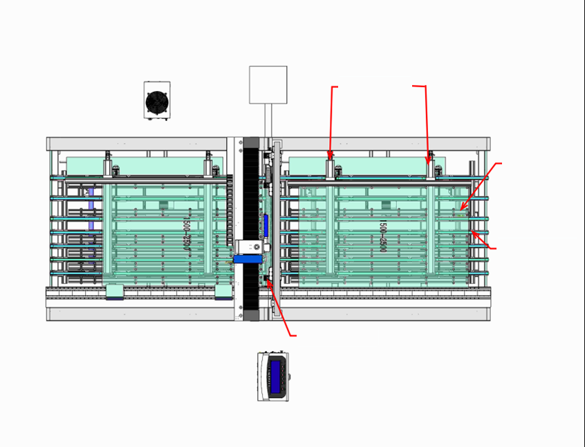
- 1Y2 grippers
- 2Lifting device
- 3Conveyor belt
- 4Vacuum port
Structure
The system comprises an electrical control cabinet, the drilling main unit, a dust collector and a laser water chiller.
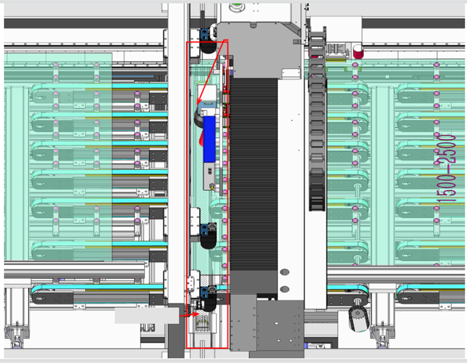
- 1Vision system
- 2Drilling zone
Vision component
Adjusts the recognition position according to different glass specifications.
Laser drilling component
Driven by the horizontal linear module to drill at any position within the corresponding area.
Glass Z-axis positioning component
Works together with the pressing unit to keep the sheet's Z-axis position consistent for every drilling operation.
Vacuum component
The extraction nozzle moves synchronously with the laser drilling component, guaranteeing extraction across any position in the drilling area.
Technical specifications
- Laser wavelength
- 1064 nm
- Average laser power
- 140 W
- Cooling
- Water cooling
- Glass thickness
- 3 mm ≤ T ≤ 10 mm
- Hole diameter
- 2 mm ≤ Ø < 65 mm (telecentric F125 lens)
- Edge chipping
- ≤ 500 μm
- Hole position tolerance
- ±0.5 mm
Processing range
- Maximum sheet size
- 2500 mm (L) × 1500 mm (W)
- Minimum sheet size
- 400 mm (L) × 150 mm (W), customisable
Control and motion
- Control system
- PLC + PC control
- Supported file formats
- dxf, plt, dwg
- Max X/Y platform speed
- 800 mm/s
- Line communication
- Inovance bus format (H5U-A8)
Power and footprint
- Total power consumption
- 8 kW
- Electrical supply
- Machine 15 kW / 380 V / 3PH · Dust collector 3 kW / 380 V / 3PH
- Overall dimensions (L × W × H)
- 6520 × 2492 × 1850 mm
- Machine weight
- 3 ± 0.5 t
Hole position tolerance assumes an incoming sheet tolerance an order of magnitude smaller than ±0.5 mm.
Machine configuration
| Item | Specification | Brand | Qty | Remark |
|---|---|---|---|---|
| Laser | 140 W (120 W / 140 W / 200 W available) | MOKE | 1 pc | — |
| Galvo scanner | 12-spot galvo | MOKE | 1 pc | — |
| F-theta lens | Telecentric F125 | MOKE | 1 pc | — |
| X-axis stage | Marble linear-motor platform | MOKE | 1 pc | — |
| Y1/Y2 stage | Linear motor modules | MOKE | 1 pc | — |
| Z-axis system | Ball-screw module | MOKE | 1 pc | — |
| Drilling software | Custom drilling software | MOKE | 1 pc | — |
| Chiller | F5300 | TEYU, Guangzhou | 1 pc | Standard |
| Vacuum fan | MCJC-2200 | Quanfeng | 1 pc | Standard |
| Industrial PC | Bus type | Inovance | 1 pc | Standard |
| Cabinet | Custom cabinet | MOKE | 1 pc | Standard |
Installation and working environment
Machine dimensions
Working environment requirements
- Voltage and frequency
- AC 380 V 50 Hz, from a supply meeting national standards
- Power
- 8 kW
- Vacuum exhaust diameter
- Ø100 mm
- Ambient temperature
- 15 °C – 35 °C; air conditioning required
- Relative humidity
- 45 % – 65 %, no condensation; dehumidifier recommended
- Electromagnetic interference
- No strong electromagnetic interference nearby; keep clear of radio transmitting and relay stations
- Foundation vibration
- Amplitude < 50 μm, acceleration < 0.05 g; avoid stamping machinery nearby
- Workshop environment
- Smoke-free and dust-free; avoid heavy-dust environments such as metal polishing and grinding
- Flooring
- Anti-static flooring and additional shielding in some environments
- Compressed air
- 0.5 – 0.8 MPa via a 10 mm line, filtered, de-oiled and dried to national standard grade 1, with connection points at both ends
Accessories supplied
| Item | Qty | Unit | Included as |
|---|---|---|---|
| Dust collector | 1 | unit | Standard |
| F125 lens | 1 | pc | Standard |
| Industrial PC | 1 | set | Standard |
| Oil-water separator | 1 | pc | Standard |
| Chiller | 1 | unit | Standard |
| Lens wiping cloth | 10 | pcs | Complimentary |
| Dust collector filter element | 2 | pcs | Complimentary |
| Servo drive | 1 | unit | Complimentary |
| F254 lens | 1 | pc | Complimentary |
| Air tube connector | 20 | pcs | Complimentary |
| Glass lifting roller | 5 | pcs | Complimentary |
| Glass conveyor belt | 1 | pc | Spare, in addition to standard |
| Cylinder | 2 | pcs | Spare, in addition to standard |
| Slider | 2 | pcs | Spare, in addition to standard |
| Tool kit | 1 | set | Complimentary |