M9070 Dual-Head Laser Drilling Machine
Two laser heads. Twice the drilling.
2 × 140 W infrared nanosecond fibre lasers
Glass thickness 1–15 mm
Hole diameter 1–100 mm
Hole position tolerance ± 0.2 mm
Glass sizes from 300 × 300 mm up to 900 × 700 mm
The M9070 is a non-contact laser drilling machine for glass and other brittle materials. Two independent laser heads work at the same time or separately, and ablate the glass with high-energy pulses.
The result is through holes, blind holes, stepped holes and special shapes, without the chipping, cracks, tool wear and cooling water of mechanical drilling.
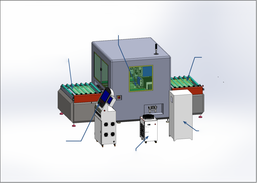
- 1Laser drilling area
- 2Infeed platform
- 3Outfeed platform
- 4Dust collector
- 5Control cabinet
- 6Dual-temperature chiller
Three working modes
Synchronous, zone-split or independent drilling with the two heads.
Drawing import
Load PLT, DXF or DWG files directly; any hole pattern within the glass.
Automatic flow
Infeed roller table, laser station and outfeed table run as one cycle.
24/7 production
Safety guards, status monitoring and fault alarms for continuous operation.
Dry, non-contact process
The laser ablates the glass with high-energy pulses: no chipping from tool contact, no cracks, no tool wear and no cooling water.
Close-hole handling
When two holes are closer than the fixed head spacing, head 2 parks and head 1 drills both, so any hole pattern is possible.
Typical applications
Appliance glass
Oven doors, hob panels, refrigerator shelves.
Furniture & decoration
Mirrors, cabinet doors, table tops, shower glass.
Building & special glass
Architectural, photovoltaic and vacuum glass.
Machine structure and working cycle
The machine has three sections: infeed platform, laser drilling zone and outfeed platform, plus the dust collector, two dual-temperature chillers and the control cabinet. Compact layout, touch-screen operation.
- 1
Infeed
The rubber rollers take the glass from upstream; a laser sensor detects it and the rollers stop.
- 2
Pre-positioning
A horizontal pusher moves the sheet to the set position, retracts, and the glass goes to the laser station.
- 3
Precise positioning
Positioning cylinders and the adjustable belt profiles fix the sheet for its size.
- 4
Dual-head drilling
Both heads move along Y to the work zone, then along X to their holes and drill.
- 5
Outfeed
The glass is sent to the outfeed table while the next sheet comes in; axes return home.
Close holes
The two heads keep a fixed distance. When two holes are closer than this distance, head 2 moves to a parking zone and head 1 drills both, so any hole pattern is possible.
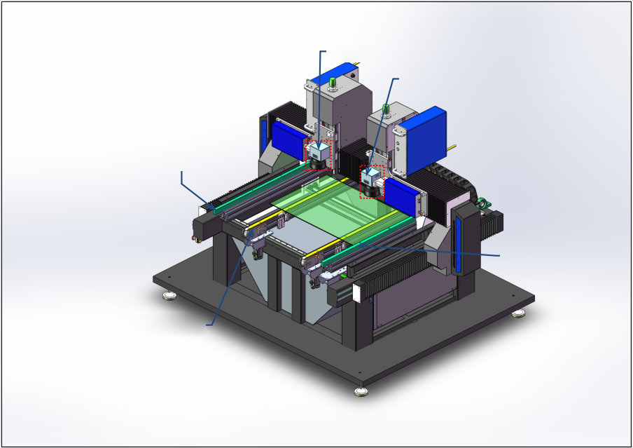
- 1Head 1
- 2Head 2
- 3Positioning bar
- 4Movable glass push strip
- 5Movable conveyor track
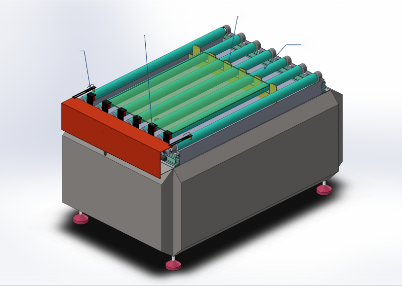
- 1Positioning baffle
- 2Fixed stop block
- 3Conveyor roller
- 4Glass detection sensor
Layout and dimensions
Front view, side view and plan view of the machine with its peripheral units. The glass runs from the infeed table through the laser station to the outfeed table.
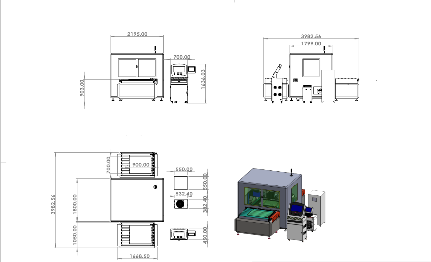
Main machine
| Dimension | Value |
|---|---|
| Overall length with infeed / outfeed | approx. 3983 mm |
| Laser station length | 1800 mm |
| Laser station width | 2195 mm (front view) |
| Infeed table length | 1050 mm |
| Working (glass) height | 903 mm |
| Glass area shown | 900 × 700 mm |
Peripheral units
| Unit | Value |
|---|---|
| Operator console | 700 mm wide · 1636 mm high |
| Chiller (each) | 550 × 550 mm |
| Dust collector | 532 × 382 mm |
| Control panel | 450 × 450 mm |
| Packing size (shipping) | approx. 4500 × 2100 × 1800 mm |
| Weight | approx. 2.5 t |
Technical specifications
- Lasers
- 2 × 140 W infrared nanosecond fibre
- Glass thickness
- 1–15 mm
- Hole diameter
- 1–100 mm
- Hole position tolerance
- ± 0.2 mm (typical)
- Glass size
- 300 × 300 mm to 900 × 700 mm
- Edge chipping
- ≤ 500 µm
Machine
- Model
- M9070
- Glass flow
- Automatic, short side leading
- Glass size
- max. 900 × 700 mm · min. 300 × 300 mm
- Glass thickness
- 1–15 mm
- Conveying height
- 900 ± 50 mm, adjustable
- X / Y speed
- 0–800 mm/s
- Footprint
- approx. 3983 × 2195 mm
- Weight
- approx. 2.5 t
- Machine power
- approx. 5.5–6 kW
Drilling performance
- Hole diameter
- 1–100 mm on ≤ 5 mm mirror / extra-clear; 1–80 mm on >5–8 mm; 1–60 mm on >8–15 mm *
- Hole position tolerance
- ± 0.2 mm (typical)
- Edge chipping
- ≤ 500 µm
- Roundness
- ≥ 90 %
- Number of holes
- Any number within the glass
Laser system (2 sets)
- Laser type
- Infrared nanosecond pulsed fibre laser
- Power
- 140 W each
- Wavelength
- 1055–1070 nm
- Beam diameter
- 7 ± 1 mm
- Pulse width
- 4–50 ns
- Frequency
- 5–3000 kHz
- Power stability (48 h)
- < 3 %
Galvo scanner (2 sets)
- Scan field per hole
- Ø ≤ 100 mm
- Scan depth
- ± 10 mm
- Scan angle
- ± 0.35 rad
- Marking speed
- ≤ 8,000 mm/s
- Linearity
- > 99.9 %
- Tracking time (X/Y)
- 0.15 ms
- Z repeatability
- < 1 µm
- Beam pointing drift
- < 20 µrad/°C
- Input aperture / beam Ø
- 12 mm / 11 mm
- Mirror coating
- 1064 nm
- Supply
- ± 24 V / 10 A
Control & software
- Control
- Syntec CNC + industrial PC
- Industrial PC
- Standard 4U industrial case, 300 W ATX industrial power supply
- Functions
- Laser energy, frequency and pulse-width setting and storage; positioning; conveying
- File formats
- PLT, DXF, DWG
- Operator panel
- Power switch, start button, emergency stop
- Dust extraction
- Built-in dust extraction fan
* The achievable hole size depends on the glass type and thickness; final values are confirmed by sample tests.
Configuration and scope of supply
Key components
| Component | Qty | Specification | Brand |
|---|---|---|---|
| Fibre laser | 2 | 140 W | Shenzhen Ouling |
| Galvo scanner | 2 | GTDS1064 | MOKE custom |
| F-theta lens | 2 | F125 / F254 | MOKE custom |
| Chiller | 2 | Dual-temperature, dual-control | Guangzhou Teyu (S&A) |
| Control system | 2 | CNC control | Syntec (Taiwan) |
Included in the delivery
Machine
Infeed roller table, dual-head laser drilling station, outfeed table, dust collector, 2 chillers, control cabinet with industrial PC.
Software & documents
Drilling software, operation manual, electrical drawings, layout drawing with connection points. PLC and HMI programs are open for maintenance.
Free spare parts and tools
| Item | Qty |
|---|---|
| Lens cleaning cloth | 10 pcs |
| Dust-collector filter | 2 pcs |
| Servo driver | 1 pc |
| F254 lens | 1 pc |
| Tool set | 1 set |
| Air-pipe fittings | 20 pcs |
| Glass lift wheels | 5 pcs |
| Glass conveyor belt (extra) | 1 pc |
| Cylinders (extra) | 2 pcs |
| Linear slide blocks (extra) | 2 pcs |
Acceptance and site requirements
Acceptance standard
| Criterion | Requirement |
|---|---|
| Reference product | Float clear glass for household appliances, 900 × 700 mm, 5 mm thick, internal holes as per acceptance drawing |
| Incoming glass | Clean surface without separating powder; slight dust is removed by a roller brush at the end of the infeed line |
| Cycle time | approx. 40–45 s per piece (acceptance drawing) |
| First-pass yield | ≥ 95 % |
| Hole diameter deviation | 0–0.5 mm |
| Hole position deviation | ± 0.5 mm (acceptance limit) |
Utilities
Power
380 V AC ± 10 %, 50 Hz, 3-phase 5-wire (L1, L2, L3, N, PE); approx. 6 kW. Earth resistance ≤ 1 Ω.
Compressed air
approx. 0.6 MPa (6 kgf/cm²), max. 200 L/min; dry, oil- and water-free (GB/T 13277 class 1).
Detailed consumption figures are confirmed after the contract is signed.
Working environment requirements
- Glass condition
- Clean, no separating powder, fixed particles or water marks
- Glass conveying
- On the centre line, short side leading, deviation ≤ ± 10 mm
- Temperature / humidity
- 20–35 °C · 30–50 % RH, no condensation
- Floor vibration
- Amplitude < 50 µm, acceleration < 0.05 g; no heavy presses nearby
- Workshop
- Free of smoke and heavy dust (no metal grinding or polishing nearby); no strong electromagnetic interference
- Chiller water
- Purified water, changed every 3 months (immediately if it turns yellow)
- Dust-collector filter
- Replace every 6 months
- Floor & grounding
- Anti-static floor and extra shielding where needed; common earth ≤ 1 Ω
- Line communication
- Inovance PLC, Ethernet interface for plant networking
Power supply
- The buyer provides a 3-phase 5-wire supply (L1, L2, L3, N, PE), AC 380 V ± 10 %, 50 Hz.
- All motors, fans and servo systems match the buyer's supply. Where a component needs a different voltage, MOKE supplies the transformer.
- The buyer brings the power cable and the main air supply to the main circuit breaker in MOKE's control cabinet and to the machine air inlet.
- MOKE provides the cable entry point, power rating and type for the machine, so that your designer can plan the power system.
Control system
- PLC with Ethernet interface for plant-wide networking, data collection and monitoring.
- All PLCs and controllers keep at least 20 % spare capacity (memory, I/O points, Ethernet ports).
- All components, actuators, cables and HMI elements carry clear labels with one consistent marking system.
- Power filtering and voltage stabilisation protect sensitive electronics such as the PLC.
- Line communication via Inovance PLC with Ethernet interface for connection to upstream and downstream equipment.
Delivery and quality
Delivery is 120 days from contract and down payment, including 5 days for technical confirmation. Every machine is assembled and tested in our factory before shipment.
Delivery schedule
| Stage | Days |
|---|---|
| Technical solution confirmed | 5 |
| Drawing design | 40 |
| Material purchasing | 35 |
| Production & assembly | 25 |
| Testing & commissioning in factory | 15 |
| Total | 120 |
Quality assurance
- All parts come from officially registered manufacturers and meet the relevant standards.
- A quality certificate is issued when the machine leaves the factory.
- The machine has all functions needed for normal production.
- All PLC, HMI and servo programs are open and editable for later maintenance.
Installation and service
Installation & training
MOKE engineers commission the machine and train your operators in drilling programs, daily checks and maintenance.
After-sales support
Remote support by phone, video and e-mail; spare parts from stock.
Send us your glass drawings. We will run sample tests and confirm cycle time and hole quality for your products.