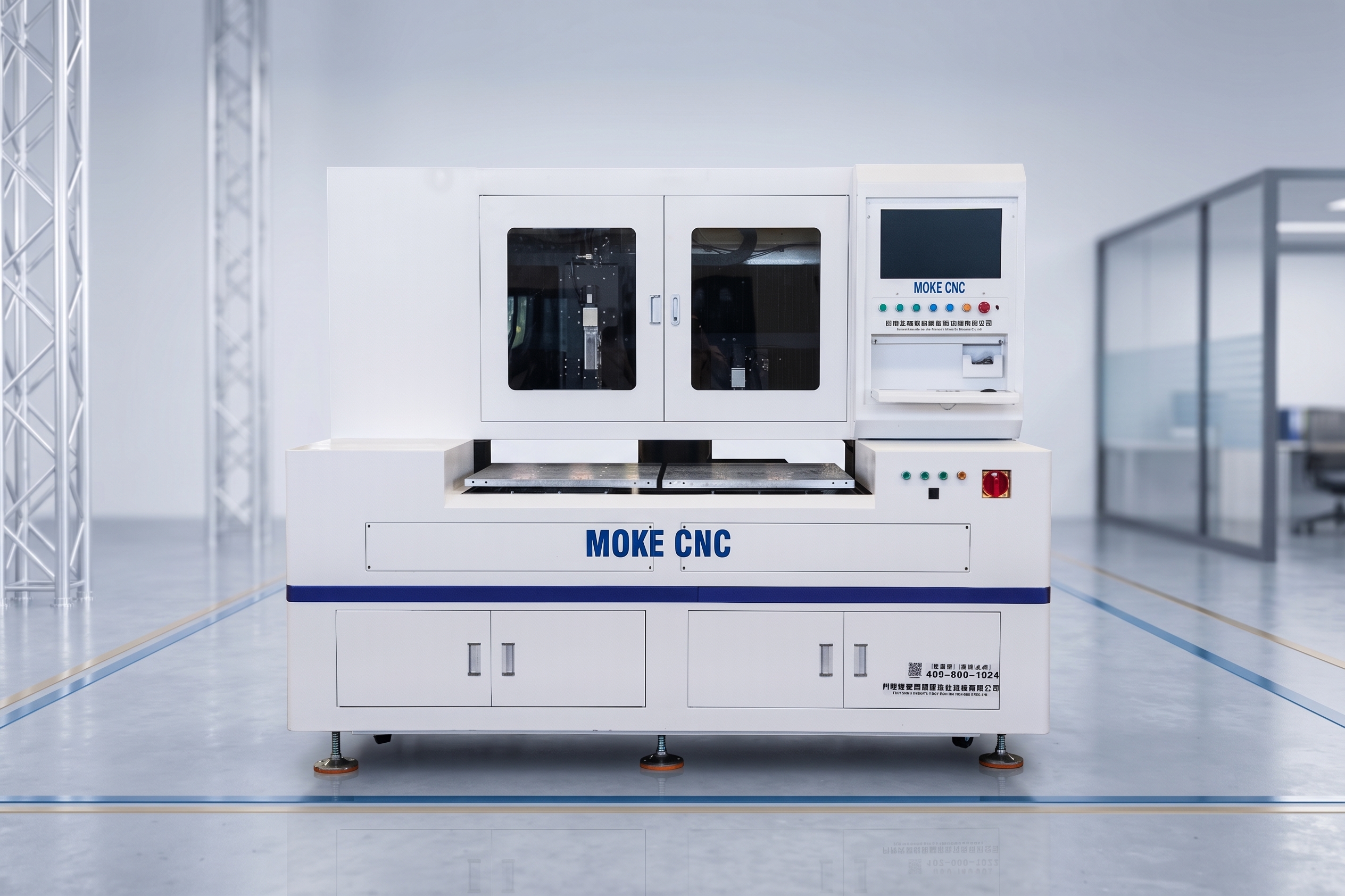
Picosecond Laser Glass Cutting Machine
Ultrashort-pulse cold processing for precise, non-thermal glass cutting
Cutting thickness 0.1 – 10 mm (depending on equipment model)
Cutting accuracy ±5 – 15 μm
Cutting speed 50 – 600 mm/s
Laser wavelength typically 1064 nm
A picosecond laser glass cutting machine is a precision glass-processing machine that uses picosecond-level ultrashort-pulse laser technology. "Picosecond" refers to 10⁻¹² seconds — one trillionth of a second. This extremely short pulse duration allows the laser to generate extremely high peak power density in glass, enabling precise, non-thermal processing.
The extremely short pulse releases its energy in an instant, avoiding heat diffusion and achieving true "cold processing". The high peak power creates nonlinear self-focusing effects inside the glass, forming a laser filament along the cut line. The laser creates micro-cracks inside the glass, after which the glass is separated along the predetermined path using mechanical or thermal stress.
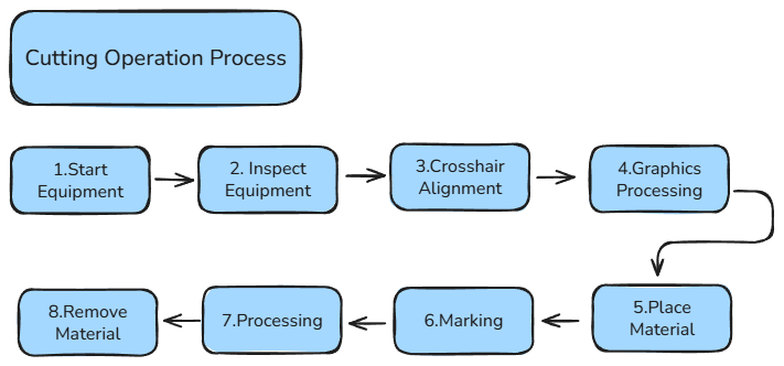
Cutting Operation Process
Suction Worktable with Dust Collection
The suction platform has a flat 600 mm × 600 mm aluminum working surface. Fixtures can be mounted on the platform to suit different products. The fixture surface is covered with suction holes of varying density, connected to the vacuum generator, which keeps workpieces flat during processing. The platform is also hollow and connected to the dust collection system: negative pressure generates a high-flow airstream that collects dust and residue produced during processing, keeping both the product surface and the machine interior clean.
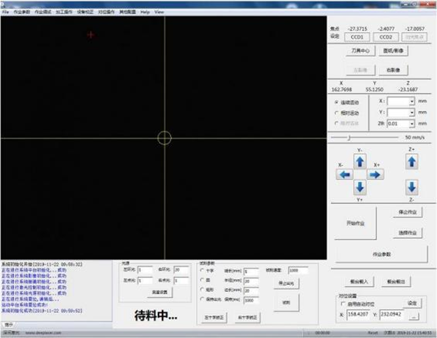
Software Control System
The software's main functions are synchronous control of the laser head, platform motion control, and graphics layer setup and drawing. The main interface includes a menu bar, standard toolbar, drawing toolbar, and main operation panel.
- Works with the CCD imaging system to recognize images and achieve precise positioning, with automatic scaling of graphics.
- Independently controls the platform, galvanometer, and I/O ports, enabling various processing modes.
- Performs basic dimensional measurement of processed workpieces combined with the CCD imaging system.
Application Fields
Consumer Electronics
Mobile phone screens and tablet glass panels.
Optical Components
Lenses, prisms, and filters.
Automotive Industry
Vehicle displays and rearview mirrors.
Medical Devices
Medical glassware and optical instruments.
Semiconductors
Glass wafers and packaging substrates.
Precision
Cutting accuracy up to ±15 μm, edge chipping below 15 μm, and taper-free cutting with excellent edge perpendicularity.
Quality
Non-contact processing with no mechanical damage. Smooth cut edges require no secondary processing, and no heat-affected zone means no changes to the internal stress of the glass.
Efficiency
Cutting speed up to 300 mm/s with one-step forming — processing efficiency several times higher than traditional CNC machining.
Environmental
No consumables and no pollutants generated. Energy-efficient and environmentally friendly, meeting green manufacturing requirements.
True Cold Processing
Ultrashort pulses release energy in an instant, avoiding heat diffusion entirely for genuine non-thermal processing.
CCD Precision Positioning
HD camera with 0.7–4.5× zoom lens enables image recognition, precise positioning, and basic dimensional measurement of workpieces.
Technical Specifications
- Processing area
- ≤ 600 mm × 600 mm
- Processing material
- Ordinary glass (surface free of dirt, scratches, etc.)
- Processing thickness
- ≤ 10 mm
- Edge dimension
- ≤ 30 μm
- Overall processing accuracy
- ±15 μm
Main Unit Structure
- Laser (2 sets)
- Picosecond infrared laser, 2.5 focal length, 80 W or other power ratings (including CO₂ laser)
- Motion mechanism (1 set)
- X/Y/Z three-axis motion system
- Optical module (2 sets)
- Bessel infrared cutting head (1–7 mm), CO₂ galvanometer module
- CCD imaging system (1 set)
- HD camera with HD 0.7–4.5× zoom lens
- Optical transmission system (2 sets)
- Beam splitter / beam expander / reflector
- Vacuum system (1 set)
- Built-in vacuum generator
- Software control system (1 set)
- Taiwan Syntec / Shanghai Cypcut
- Mechanical structure (1 set)
- Welded steel structure + marble base
- Suction platform (1 set)
- 600 mm × 600 mm
X·Y·Z Platform Performance
- Effective processing stroke
- X: 750 mm · Y: 800 mm · Z: 50 mm
- Effective area
- X: 600 mm · Y: 600 mm
- Maximum movement speed
- X: 600 mm/s · Y: 600 mm/s · Z: 25 mm/s
- Positioning accuracy
- X: ±3 μm · Y: ±3 μm · Z: ±10 μm
- Repeatability
- X: ±2 μm · Y: ±2 μm · Z: ±5 μm
Cutting Laser (Picosecond)
- Wavelength
- 1064 nm picosecond laser
- Power
- 70 W
- Repetition frequency
- 50 kHz – 1 MHz
- Pulse width
- < 10 ps
- Energy stability
- < 3 % RMS over 8 hours
- Beam quality
- M² < 1.3
- Mode
- TEM₀₀
Breaking Laser (CO₂)
- Wavelength
- CO₂, 10.6 μm
- Power
- 100 W
- Beam quality (M²)
- ≤ 1.2
- Rise time
- < 75 μs
- Energy stability
- < 3 % RMS over 8 hours
Equipment Factory Conditions
- Power supply
- Three-phase 380 V AC, 50 Hz, 20 A
- Compressed air
- 0.6–0.8 MPa, quick connector, 10 m air pipe at the machine end, air consumption 160 L/min
- Floor load
- 500 kg/m²
- Equipment dimensions
- 1350 (L) × 1850 (W) × 1665 (H) mm (main unit only)
- Installation space required
- 3000 × 3000 × 2500 mm
- Main unit weight
- Approximately 2 tonnes
- Ambient temperature
- 22–25 °C, variation within ±1 °C per 24 h
- Ambient humidity
- 40–70 % (no visible condensation)
- Cleanroom class
- Class 100,000 or better
- Power consumption
- 6 kW
Note: Laser parameters and performance can be accommodated through customization to meet special requirements.
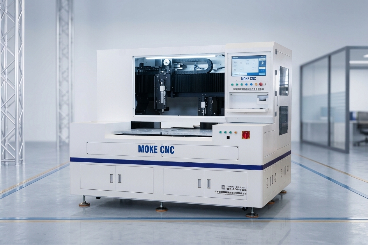
Machine Photos