Laser Drilling Line 1 (3 Lasers)
Three lasers in one line for high output
3 laser drilling machines in series
Max. glass size 2500 × 1300 mm
Glass thickness 3–12 mm
Total line length approx. 20.7 m
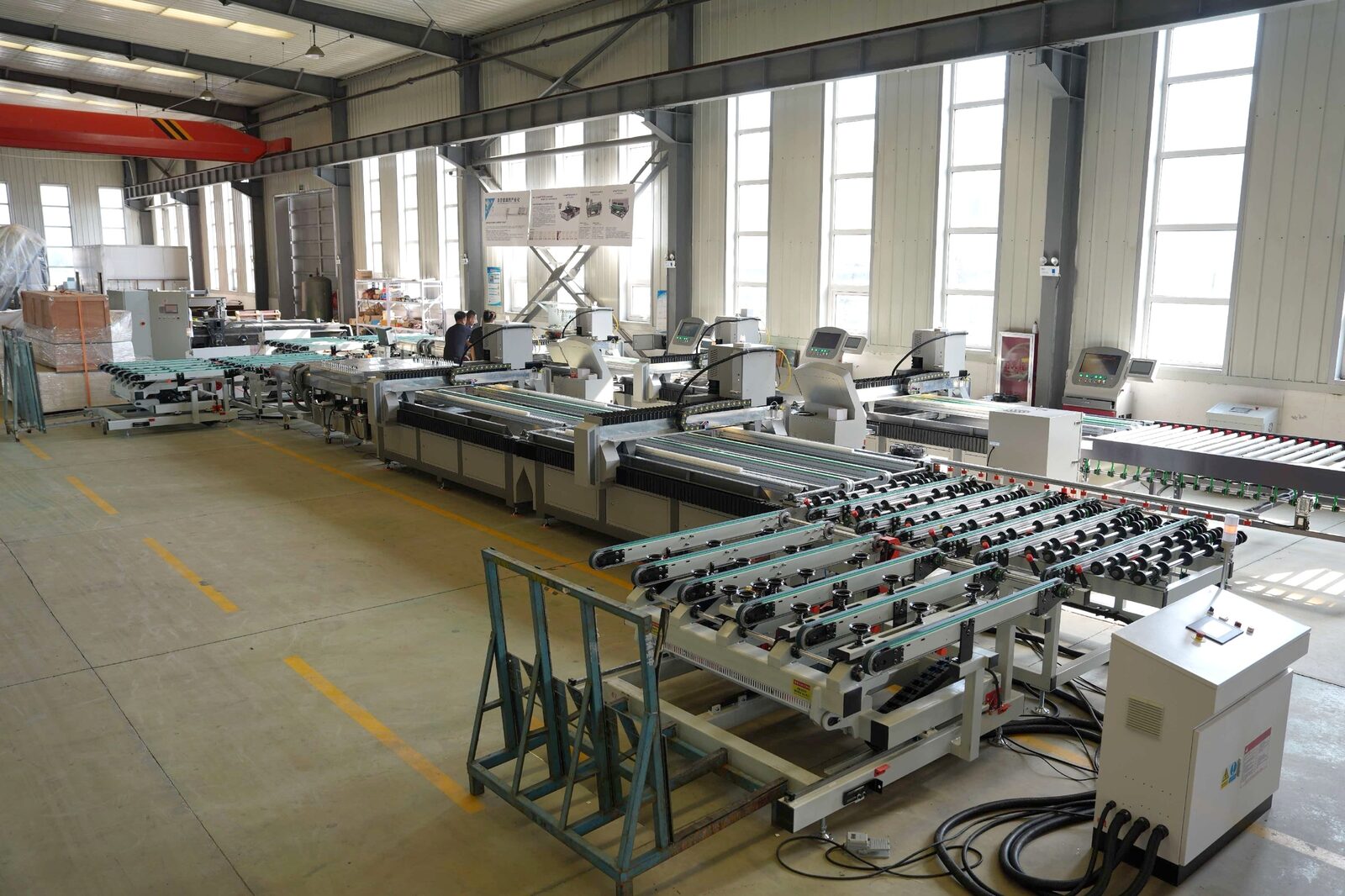
Glass enters on the infeed table and passes three laser drilling machines in series, which share the drilling work. The sheet is then washed, dried and stacked on the rack by the automatic unloading table.
Two to three operators per shift run the whole line.
Why customers choose this line
High output
Three lasers work on the same sheet in turn, so each machine drills only part of the pattern.
Dry, non-contact drilling
No drill bits, no cooling water at the laser, no tool changes. Round and special-shape holes from a DXF file.
Clean glass at the outfeed
Brush washing, three-stage spray and infrared drying. Glass leaves the line ready for the next process.
Automatic stacking
The tilting unloading table places every finished sheet on the rack and warns when the rack is full.
Safe by design
Class 1 enclosed laser, emergency stops along the line and anti-collision interlocks between stations.
Supported on site
MOKE engineers install, commission and train your team at your plant.
Layout and process flow
- 1
Infeed
The sheet is placed on the infeed transfer table (manually or from an upstream line).
- 2
Positioning
The transfer table aligns the sheet and feeds it into laser 1.
- 3
Laser drilling ×3
Each laser re-positions the sheet, drills its part of the pattern and passes it on.
- 4
Washing & drying
Brushes, three-stage spray and infrared ovens remove all dust and slurry.
- 5
Positioning for unloading
The clean sheet is aligned on the unloading table.
- 6
Automatic unloading
The tilting arm stacks the finished glass on the A/L rack.
Dimensions
| Dimension | Value |
|---|---|
| Total line length | 20704 mm |
| Working (conveying) height | 900 ± 50 mm |
| Laser drilling machine length | 3560 mm |
| Laser machine width | 2436 mm |
| Laser conveying width | 1350 mm |
| Laser machine height | 1820 mm |
| Gap between machines | 100 mm |
| Washer length | 3900 mm |
| Washer width | 1770 mm |
| Infeed transfer table | 2800 × 1500 mm |
| Unloading table (along × across line) | 2500 × 3825 mm |
| Unloading operator panel | 380 × 560 mm |
All dimensions in mm, for reference only. The final layout drawing is supplied with the quotation.
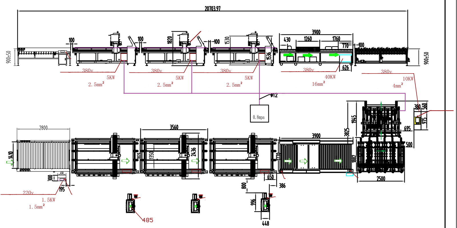
On the drawing
- Compressed-air source 0.8 MPa, Ø12 mm air line to each machine
- RS-485 main communication control cabinet
- Supply voltage / power / cable size of each module (see site requirements)
- Electrical cabinet of each module
- Emergency stop button
- Laser-head side of the machine
- Glass flow direction, left to right
- Washer water tanks 1–3 · two 340-type infrared ovens
Modules and specifications
Module 1 · Automatic unloading table and transfer tables
At the end of the line, a tilting arm with vacuum suction cups moves the glass between the belt table and an A- or L-type storage rack. The table body travels on floor rails to the rack. Transfer tables convey and position the glass between the machines.
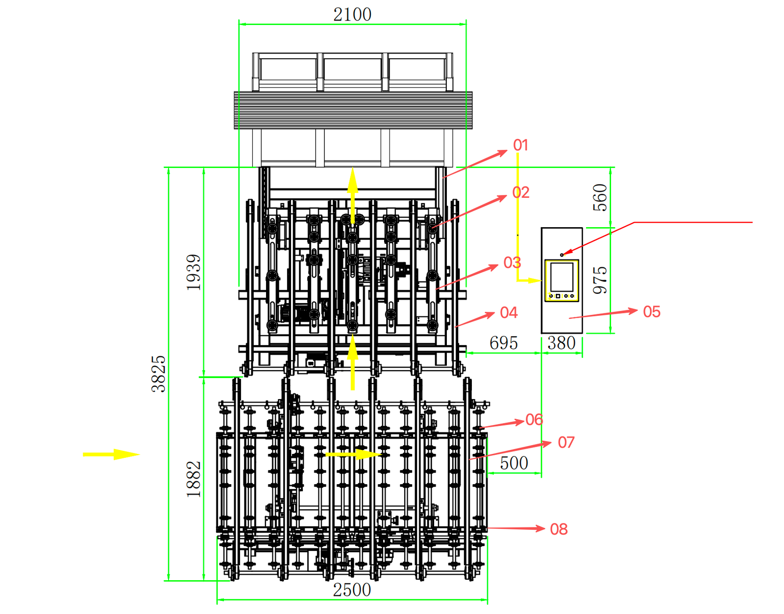
- 1Emergency stop button
- 23-phase 5-wire 4 mm² power cable
- 3Unloading direction
Unloading table · CRLU2201
- Max. glass size
- 2500 × 1500 mm
- Min. glass size
- 500 × 300 mm
- Glass thickness
- 3–12 mm
- Cycle time
- 10–15 s per sheet
- Rack depth
- 750 mm
- Table height
- 920 mm (adjustable)
- Power
- 6.5 kW · 380 V 50 Hz
- Weight
- approx. 1390 kg
- Dimensions
- 3825 × 2500 × 920 mm
Max. glass size of the table itself. Line maximum 2500 × 1300 mm, limited by laser travel and washer width.
Small-size mode
Faster arm motion profile for small sheets to raise throughput.
Rack-full warning
The table measures the stack and asks for a rack change in time.
Vacuum gauge & fault alarm
The panel shows vacuum pressure and signals faults before glass can slip.
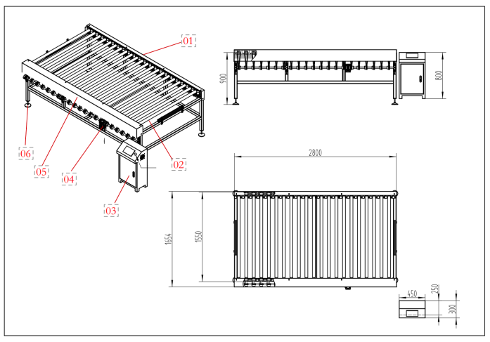
- 1Guard cover
- 2Conveying rollers
- 3Electrical cabinet
- 4Conveyor motor and gear reducer
- 5Guard
- 6Levelling feet
Transfer tables · CRTT2508-S / -A
- Function
- Convey and edge-position the glass between stations
- Power
- 1.5 kW · 220 V 50 Hz
- Dimensions
- 2800 × 1500 × 900 mm
- Control
- Own PLC + HMI touch screen
Module 2 · Laser drilling machine CRLC1830 × 3
A pulsed fibre laser with a high-speed galvo scanner drills the glass without contact. Each machine positions the sheet again on arrival, drills its part of the pattern and sends the sheet on automatically.
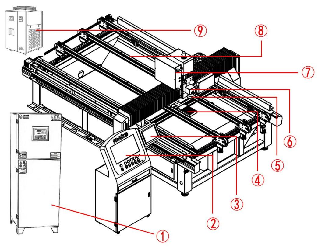
- 1Dust collector
- 2Main control screen
- 3PLC control screen
- 4Vacuum suction unit
- 5F-theta lens
- 6Galvo scanner
- 7Laser source
- 8Conveyor belt
- 9Dual-circuit chiller
Laser drilling machine · CRLC1830
- Laser
- Pulsed fibre, 1064 nm
- Working travel
- X 1300 · Y 2500 · Z 200 mm
- Scan speed
- up to 12000 mm/s
- Focal spot
- 0.1–0.2 mm, adjustable
- Control
- Syntec CNC + PLC, Ethernet link to the line
- Cooling
- Industrial chiller, 25–28 °C
- Power
- ≤ 4.5 kW · 380 V 50 Hz, 3-phase
- Compressed air
- 0.4–0.6 MPa
- Weight
- approx. 1200 kg
- Machine body
- 2300 × 3000 × 1750 mm
- Overall incl. conveyor and cabinet
- 3560 × 2436 × 1820 mm
What it can do
Drilling
Round and special-shape holes, drawn on screen or imported as DXF.
Cut-outs
Slots, stars, sockets and other contours in the same program.
Frosting & coating removal
Sandblast effect and mirror back-paint removal (manual mode).
Enclosed, dust-free
Negative-pressure chamber; dust is extracted and filtered at source.
Stable accuracy
Stress-relieved welded steel frame, deformation ≤ 0.01 mm.
Class 1 laser product
Beam fully enclosed in a multi-layer metal housing during operation.
Module 3 · Glass washing and drying machine CRWD2600C
A horizontal washer removes glass dust and slurry after drilling, then dries the sheet completely, so it leaves the line clean and free of water marks.
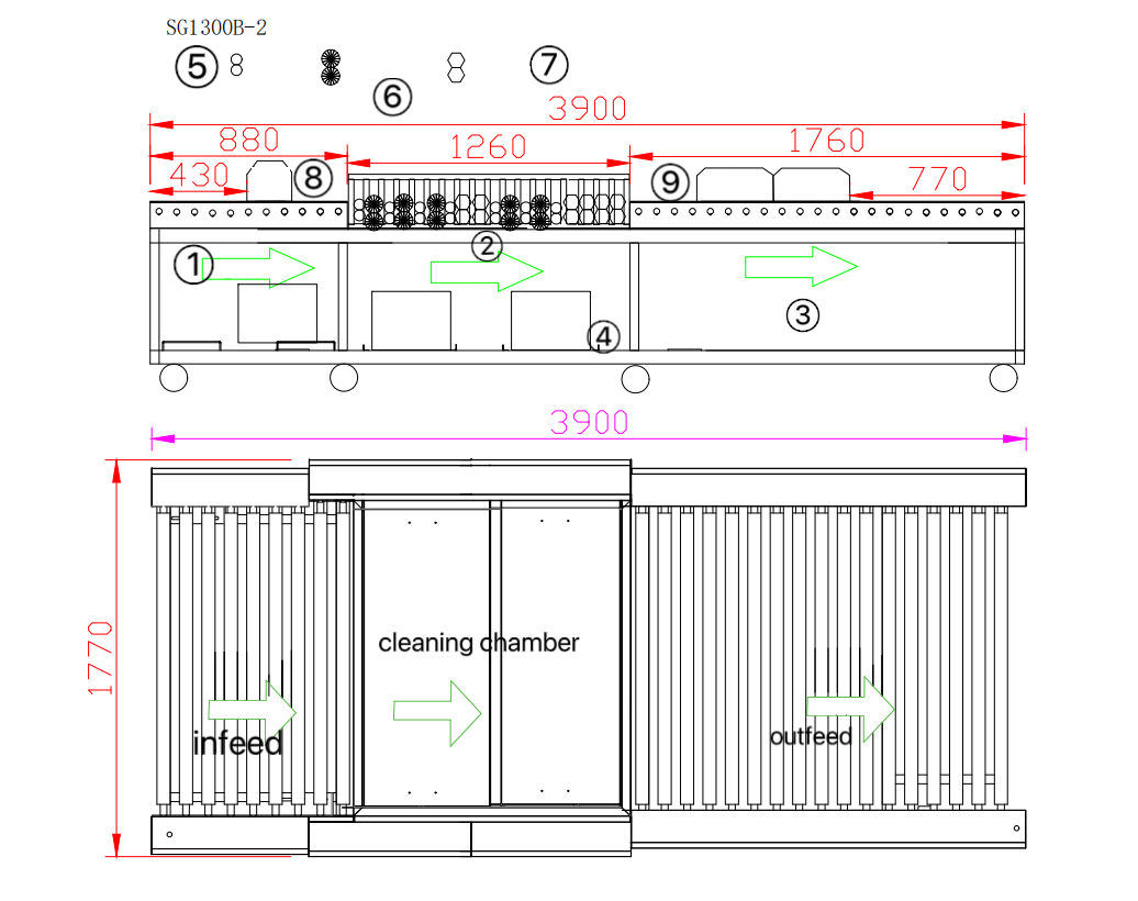
- 1Pre-spray
- 2IR ovens
Washing & drying machine · CRWD2600C
- Glass thickness
- 2–12 mm
- Max. glass width
- 1300 mm
- Conveying speed
- 1–5 m/min, frequency controlled
- Washing
- 5 pairs of nylon brushes + 3-stage spray
- Drying
- Two infrared ovens, 3 heating elements each
- Total power (incl. two IR ovens)
- 40 kW · 380 V 50 Hz, 3-phase 5-wire
- Compressed air
- 0.3–0.6 MPa
- Dimensions
- 3900 × 1770 × 1020 mm
Three-stage spray
Pre-wash, main wash and pure-water rinse; neutral detergent can be used.
Three-tank filtration
Cascade tanks recycle the water and keep stages separate.
Soft on glass
Wear-resistant NBR rollers at 80 mm pitch and sponge rollers that absorb the water film.
Simple utilities
Tap-water inlet through a filter and one drain to your workshop system.
Safety built into every station
The line is designed and documented for CE marking. Guards, interlocks and emergency stops protect the operators during automatic production.
Enclosed laser
The 1064 nm laser runs inside a multi-layer metal housing. The complete machine meets Class 1 (safe in normal operation). Two pairs of laser safety goggles are supplied for service work.
Emergency stops along the line
Mushroom-head E-stops on the infeed transfer table, every laser cabinet, both ends of the washer and the unloading table panel.
Interlocks between stations
Photoelectric sensors and first-in-first-out queue logic stop the conveyor before sheets can collide.
Vacuum gauge & fault alarm
The unloading table shows the vacuum pressure and gives a fault alarm.
Locked electrical cabinets
All cabinets are locked with triangular keys; only qualified technicians can open them.
Customer fencing
The swing area of the tilting arm must be fenced or protected by light curtains on site, to local regulations.
Noise (at 1 m, full load)
| Module | Sound pressure level |
|---|---|
| Laser drilling machine | ≤ 65 dB(A); 68–72 dB(A) with the dust collector running |
| Unloading and transfer tables | ≤ 65 dB(A); short pneumatic exhaust (< 2 s) |
| Washing machine | ≤ 72 dB(A); ear protection recommended for long stays nearby |
What your site needs to provide
Each module has its own electrical cabinet. You bring power, compressed air and water to each cabinet; MOKE supplies a layout drawing with every connection point marked.
Power (per module)
| Module | Supply | Supply rating (max.) | Cable |
|---|---|---|---|
| Infeed transfer table | 220 V AC single-phase (L, N, PE) | 1.5 kW | 1.5 mm² Cu |
| Laser drilling machine #1, #2, #3 (each) | 380 V AC, 3-phase 5-wire | 5 kW | 2.5 mm² Cu |
| Washing & drying machine | 380 V AC, 3-phase 5-wire | 40 kW | 16 mm² Cu |
| Unloading table + outfeed transfer table | 380 V AC, 3-phase 5-wire | 10 kW | 4 mm² Cu |
| Total connected load | ≈ 66.5 kW |
Supply ratings are the maximum each feed must be sized for. Typical consumption is given on the module cards: laser drilling machine ≤ 4.5 kW, loading / unloading table 6.5 kW, transfer table 1.5 kW.
Compressed air
Dry, oil-free air from a 0.8 MPa source, Ø12 mm line to each laser and the unloading table. At least 0.6 MPa at the unloading table.
Water
Tap-water inlet through a mechanical filter, and a drain with a steady fall to the workshop drainage.
Floor
Flat, solid concrete without voids or expansion joints. Levelling ≤ 1 mm/m (washer ≤ 2 mm/m). Anti-vibration pads recommended.
Cabling
Main cables from your distribution board to each cabinet (trench or overhead tray) are by the customer.
Module footprints
| Module | L × W × H (mm) | Weight |
|---|---|---|
| Complete line 1 | approx. 20704 long | – |
| Laser drilling machine CRLC1830 (each) | 3560 × 2436 × 1820 (overall incl. conveyor and cabinet) | ≈ 1200 kg |
| Washing & drying machine CRWD2600C | 3900 × 1770 × 1020 | – |
| Unloading table CRLU2201 | 3825 × 2500 × 920 | ≈ 1390 kg |
| Transfer table CRTT2508 | 2800 × 1500 × 900 | – |
Delivery, installation and support
- 1
Delivered ready to place
Every module ships as a complete, self-contained machine. No structural assembly on site; position with a forklift or crane.
- 2
Installation & commissioning
MOKE engineers come to your plant to align the line, set the laser origins, check cabling and piping, and commission the system.
- 3
Operator training
Hands-on training for unloading, laser programming (DXF import, hole set-up), washer operation and daily checks.
- 4
Documentation
Full operation manual, electrical and mechanical drawings, layout drawing with connection points.
Options and configurations
Number of lasers
Three lasers for maximum output; a two-laser version (Line 2) is also available.
Automatic loading
Add a loading table at the infeed for rack-to-rack automation.
QR-code job loading
Handheld scanner: scan the glass, the right program loads and starts automatically.
Frosting & coating removal
Use the same lasers for sandblast effects and mirror back-paint removal.
Easy daily care
| When | What |
|---|---|
| Daily | Clean vacuum cups, sensors and laser lenses; check chiller temperature (25–28 °C); flush washer tank 1 and empty the chip filter |
| Weekly / monthly | Drain air-filter condensate; lubricate chains and gears; check brushes, sponge rollers and belts |
| Spare parts | Recommended spare-parts list for lasers, washer, tables and conveyors supplied with the line |